Panel Hole Patterns Standards
Panel Hole Patterns Standards
Tools: Panel Hole Patterns Standards
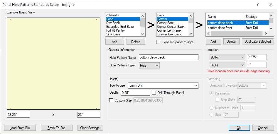
This section is designed to setup the default hole patterns to be added every time a certain cabinet is placed. This section is NOT where hole patterns for adjustable shelves is set. Some applications for this would be setting up hinge patterns on panels for doors or holes for peg feet to be put on cabinet bottoms. The first 3 sections are designed to flow from left to right and that is the order that they are described in below.
- Example Board View: This is an example board view to display where the holes will be placed on whatever panel is specified.
- Cabinet Type Selection: By default, the <default> will cover all cabinets. By clicking on Add, defaults can be set up for various parts on specific cabinets.
- Part Selection: After the type of cabinet (or <default>) is selected, individual parts can be selected for hole patterns to be added. Depending on the part selected for creating the hole patterns on, there is an option to clone left panel to right.
- Strategy Area: This section lists all of the strategies for the parts selected in the default cabinet or for types of cabinets. Once each section is filled out from below, a name is attached to that strategy and listed in this section, with the tool that is used for that strategy next to it. To begin adding strategies, click on Add. Strategies can also be duplicated for easy reversal for line bores or can be deleted.
- General Information: This area has 2 fields, a place to name the strategy and a choice between the different Hole Pattern types which are Hole (for single hole creation) or Line (line bore).
- Location: This sets up the location of the single hole or start of the line bore. If Line is selected, the Extending will be set up in a different field. CAUTION! HOLE LOCATION DOES NOT INCLUDE EDGE BANDING, so please adjust for edge banding in measurements this section before cutting parts.
- Hole(s): This area holds the information for which tool will be used to cut with (brought in from the EnRoute Tool Library). It also sets the depth of the hole or put a check next to Drill Through Panel to bypass the depth and drill straight through. If the hole is a different size than the tool itself, that can be specified by putting a check next to Custom Size. Remember, only do this if the tool used is NOT a drill bit.
- Extending: This section is only lit up if Line Bore is selected.
- Direction (Towards): This section determines the direction of the line bore from wherever the location is set above, towards the bottom, towards the top, Front (left), or Right (Back).
- Parametric: By default this option is selected. Using the options selected in the other areas of this window, the line bore will travel along the location that is selected, placing holes at 32mm increments.
- Stop Short: With this selected, the parametric line bore will stop at the specified distance away from the edge of the panel.
- Number of Holes: With this selected, a specified number of holes will be placed parametrically, again in the same direction as indicated in the options in the window above.
- Size: This option specifies a certain length that parametric holes will be only be placed in the panel.
- Load From File/Save to File/Clear Settings: The settings created in this section can be saved to a specific file name or loaded from that specific file. Settings can also be cleared from this window.